Saturday, March 31, 2007

Fitting the wheels


I've been thinking about how to fit the wheels for some time ("putting it off" might be more accurate). Seems that people have their own methods, and the instructions touch on this only briefly. I've looked at the design for a jig that fits wheels (and does the quartering) by tightening it a vice. But an Association member who builds his own locos successfully with relatively simple tools has described his method for fitting and quartering wheels which I plan to follow.

First file a chamfer on the end of each wheel axle


I'd already opened up the muffs with a 1.5mm drill. Now I need to drill a 1mm hole through the centre of the muff. This is to allow release of air as the tight-fitting axles are pushed in.


A final check that the chassis sides are still electrically separate, then I fit the first axle by turning each wheel by hand with gentle pressure inwards.


I've put a small washer on this axle to reduce sideways play.

I'd previously calculated that I needed a 0.45mm gap on each side between the wheels and chassis and now I need some spacers.

simple styrene sheet spacer

The key dimension is the distance between the back of the wheel rim and the chassis side. So the gap in the spacers has to be big enough to go around the small raised section visible around the axle, allowing the spacer to lie flat against the wheel. I cut some from 0.5mm thick styrene sheet.

Now with the spacers in place I can gently twist both wheels inwards until they are tight against the spacers. The first axle turns freely so I do the same with the central axle.

spacers on central axle

Now the gears are locking. Even though they had previously been running smoothly, I have to spend quite a while running the wheels along the test track by hand to loosen them up again.

Next to add the final axle, tighten the wheels to 8.5mm back-to-back (or just over) and turn the wheels so that the balance weights are aligned on both sides, with a quarter-turn difference between sides.


Sunday, March 25, 2007

The coupling rods


The good news here is that because I've chosen to fit gears to drive all the axles, I don't need to worry too much about getting the coupling rods and crankpin relationship spot-on.

coupling rod etch

That small piece was loose when I first opened the box. I've been worried about losing it ever since so it'll be good to get this done.


Soldered, filed, the holes opened with a broach then finished with wet-and-dry.


The pins are a good tight fit, but I may need to make the holes larger to get things running when I fit the cranks on the wheels.


** May 2007 **

When I examined my prototype more closely I realised there was some more work to be done. The overlays around the crankpins are circular, and very thin. I tried to represent this by filing the overlays thinner and rounding the edges as much as I could.

the lower rod here has been trimmed

Thursday, March 22, 2007

Fitting the crankpins


OK, I've changed my mind. Having thought a bit longer, I'm planning to fit the crankpins to the cranks, then fit the wheels then add the cranks.

Three reasons:

I'm finding it difficult to accurately fix the cranks parallel to the wheels.

I don't want to find that the cranks need to be adjusted further down the line.

I can make the crankpin joints stronger if I do them "on the bench".

And also, the instructions suggest doing it this way.

So, how to get the crankpins fixed perpendicular to the cranks? With the crank in a parallel clamp, I can hold the pin in the correct position with a finger while I solder (yes, the pin gets hot very quickly).


Then hold them in a drill chuck to tidy them up. I managed to get some solder around the sides of the cranks making the fold-over joint less obvious.


And now I can use the pins to help align the cranks on the wheels.

Wednesday, March 21, 2007

Wheel balance weights


etch with 6 weights (larger weights for the central wheels)

Once removed from the etch these proved to be a test of patience. They're the size of a small fingernail clipping and have to be gripped tightly while the brass sprue is filed away (I use my small parallel clamp for tricky cases).

I fixed them with epoxy, and cleaned the excess off with fine wet-and-dry paper.


They look good, but I know I've got it wrong - the small weights are correct but I'm pretty sure the ends of the larger weights should lie mid-way between spokes not on the spokes as I've positioned them. I can't take them off without risking damage to the spokes so I'm stuck with them :-(

Worse things happen, but I'm disappointed - I think this is my first mistake that I haven't been able to correct.

** 28 March 2007 **

I hadn’t thought of trying to dissolve the glue but after seeing Nigel’s comment I checked on the 2mm Association Yahoo Group for suggestions. There were some posts suggesting using acetone for this.

Didn’t have any acetone handy, but thought I could try Plastic Weld (dichloromethane) which works by dissolving styrene.

This did make the glue soft enough to be scratched away with a pin-head, so I’ve now replaced the large weights in the correct position.


Tuesday, March 20, 2007

Checking out the cranks


I've decided to go with Humbrol matt black for the wheels. I'd rather use paint than any strong chemicals to colour the wheels, as they could get onto the rims and damage the running surface.


Just a first coat - I'm thinking I should fit the wheels before the second coat. But so far it looks quite pleasing.

I need to fit crankpins to the cranks and the cranks to the wheels. Opinion seems to be divided about what should be done before fitting the wheels and what after. The crankpins are so delicate, it seems to make sense to fit the wheels before adding them, but no harm in doing a "dry run" first to see what it all looks like.

crank etch

soldered and trimmed

As can be seen I had trouble getting a smooth edge on the cranks. Perhaps more solder would have helped fill those gaps?


trial fitting of cranks

There's plenty of room on the extended axle for the crank. Should it be close to the wheel or at the outer end of the axle?


With the wheels pushed closely together in the underframe, it looks as though there is still room for the crank well down the axle. Probably best to allow some margin for error though, so I'll put the cranks part-way down.

with a crankpin

These are a very generous length. I'm not sure exactly when I'll have to trim them, but even if I cut them short now, they'll still get in the way when I'm fitting the wheels onto the muffs.

Meanwhile I've realised, having painted the wheels, that I've forgotten to fit the balance weights.

Best plan now seems to be, to fit cranks and balance weights, re-do the paintwork, fit the wheels, get the quartering as good as possible by eye then add the crankpins and finalise the quartering.

Sunday, March 18, 2007

Some chassis adjustments


There's a few things I need to tidy up.

When I fitted the rear spacer on the chassis I made it quite short. Now I'm thinking it may be useful to have it a bit longer, to give support to any coupling I may want to fit.

Extra spacer glued on

I haven't decided on a coupling system as such, but I will certainly want a coupling hook which I'll be able to secure on the inside with this extra spacer.

One thing that's been bothering me, is that the muff on one of my stub axles is short and moves from one side to the other when the gears change direction. It doesn't appear to affect anything, it's just annoying. I've been looking for some suitable washers for a while, but eventually find something in my "might be useful someday" box.

I think these nuts came with the Peco N-gauge wagon kits. Inside diameter is pretty near perfect for my axle steel, I just need to file one to rather less that half its width.


Works well. I could do some even thinner ones for the other muffs, but with a big model railway exhibition coming up I'll see if I can get anything there first.

Now to blacken the chassis sides (again).


I think only the lower part will be visible to any extent. I just slapped some more blackening liquid on the existing surface, taking care to avoid the spur axles. I think it's produced an interesting effect - messy black in a slightly uneven way.

Saturday, March 10, 2007

Thinking about painting


I’m now reaching the point when I need to start putting the various parts together. But some parts would be better painted first, which is giving me a headache at the moment.

Of all my modelling skills, such as they are, painting is probably the weakest. I don’t want to spoil my lovely model with poor paintwork, but looking at the “wasp stripes” on the loco ends is quite dispiriting - I know I couldn’t do that justice with my current level of skill.

Photo: Paul Appleby in Rail Photo Archive

There are also large flat areas on the sides and having just practiced with my best paintbrush, some enamel paint and an old piece of brass, I’m not sure I can even do a flat surface free of brush marks.

I’m considering three options:

1) Finish as much of the work as possible while I wait for inspiration (current plan)

2) Pay someone to do a proper job (sounds good, but might be complicated)

3) Complete it unpainted, with key parts removable for painting at a later date

I’m completely undecided over this at present, but there is some good news. Almost everything below the footplate is shades of dirty black, and my chassis, even after ten weeks of manhandling still has some of the original blackened areas. Once the wheels are on I wouldn’t expect this area to get that sort of treatment so I’m going to blacken the chassis again then put the wheels and coupling rods on. This way I can put off any decision for another few weeks.

Meanwhile I need to practice my brushwork, experiment with masking tape, and develop an idea for a stripe-painting jig.

Monday, March 05, 2007

The footplate overlay


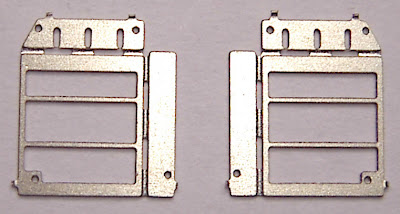
The footplate overlay etch has to be secured onto the underframe. It must remain flat for a quality result, I’m told. A bad start when I cut it from the etch and it springs into a banana-shape.


There are holes for screws at each end to secure it to the chassis. My kit included 10BA screws but I’d ordered some 12BA as these were recommended by others building this kit.

Think my best chance of a secure join is a generous portion of Araldite with the screws locating it in place. Once set I check that the sections are still electrically isolated, then have to file away the excess glue squirting out the sides.

I’d filed the PCB footplate side smooth earlier, but now I look again there are a couple of places still looking a bit uneven. I fill these with a smear of superglue and file away when set.


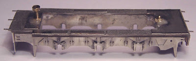
The photo shows that the edge is still not as smooth as I’d like. This will be very obvious on the finished model, so I give it a few strokes of fine wet and dry paper. This photo also shows a gap where the PCB footplate is shorter than the etch. I need to make up the front steps to check the correct length.


Laying the steps in place, turns out the clearances are very tight here. I have to file the footplate back to make room for the steps.


The steps shouldn't protrude forwards beyond the front bufferbeam. I've filed the footplate right back so the steps will be in contact with the front sandboxes (to fit in those recesses on the side frames).

Finally the nuts have to be soldered over the holes in the overlay. Wanted to be sure I got this exactly right so I tried to solder around the outside of the nut with the screw already through it. Hopeless - as I half-expected, I soldered the screw onto the nut. Found it much easier with quick-setting glue. I hadn't really used this stuff in the past, but I'm definitely getting to like it.