Sunday, December 31, 2006

Blackening the chassis

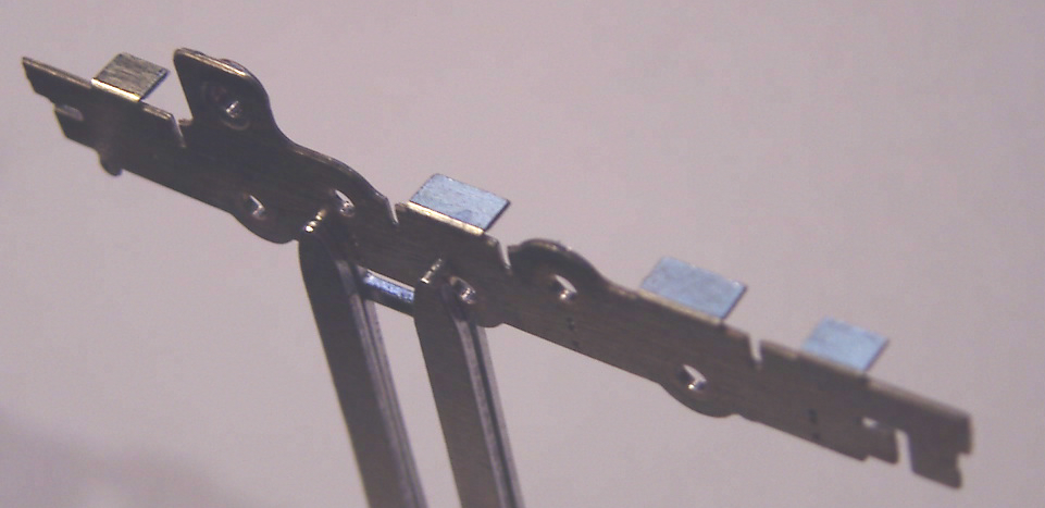
The underframe of the loco will obviously have to be a dirty oily colour when it’s done. I’m hoping I can get away without painting a lot of small delicate parts if I blacken them first.

I don’t think much of the chassis will eventually be visible, so this would be a good place to see how well it works.

I bought some Birchwood Casey Liquid Blue once, planning to reduce the shine on the top of my rails. Haven't got round to that yet, but have used it for chemical blackening. It’s strong stuff (used on rifle barrels, apparently), and needs to be washed off in water as soon as the required colour is reached. I paint a little on a spare part of etch, and it starts to colour after a few seconds.

They give instructions on how to prepare the surface with some products I don't have, so I use liquid flux and wash off after a minute or so.


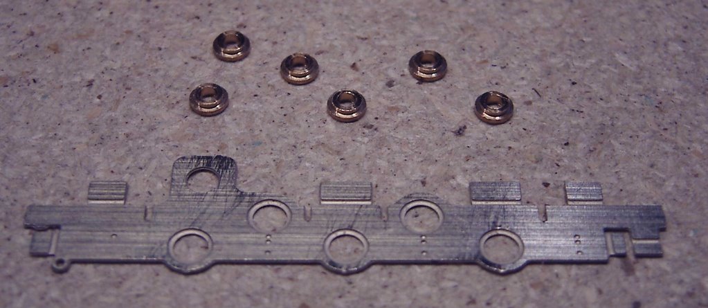
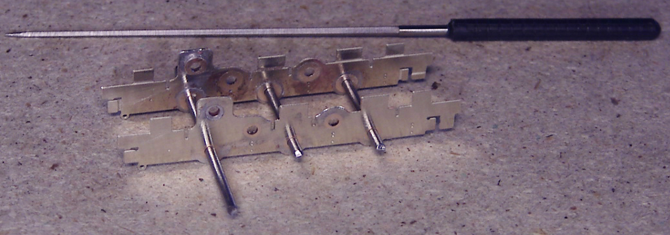
the chassis prepared with flux


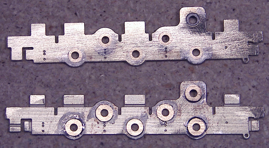
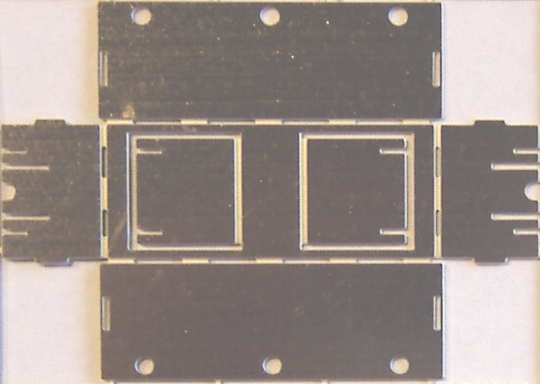
after blue-ing for 10 seconds


30 seconds

I'd say this was a good colour, but there were a few stubborn bits refusing to blacken.
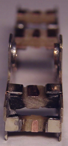
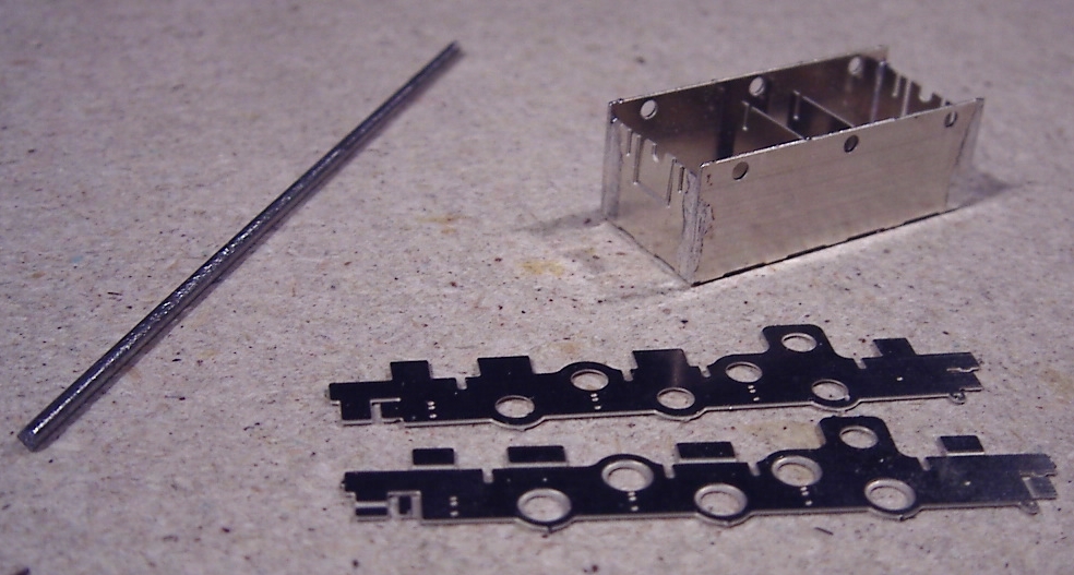

60 seconds

Perhaps I didn't prepare those areas well enough.


Now with a small dab of lubricating oil smeared over.

This looks quite promising, but the black layer can come off. I'll leave one side oil-free and see how it looks after being handled for a couple of weeks.

Sunday, December 17, 2006

Testing the gears


When I read the instructions for this kit and found that there were several ways of putting the gears together my first thought was that I’d go for the simplest layout. But this would mean two of the axles being driven by the coupling rods, and since I’ve had problems with this before (my Farish conversion), I’m coming round to the idea of driving all the axles via gears.


The 18 tooth gears with muffs

The muffs turned out to vary in length from 5.95mm to 6.11mm. I decided to use the shortest one for the worm wheel, as by filing the inside of the corresponding axle bearings I could make the muff a perfect fit.

Worm wheel bearing

Wondering what effect this difference in lengths will make when the muffs are in place. Perhaps I should get some small washers to act as equalisers for the shorter muffs.

The gears can be pushed onto the muffs, but the hole through the muff is (deliberately) too small for the axles, and needs to be opened out until the axle will slide in tightly.

I want to put the gear wheels together on the chassis to check that it all runs freely, but I’m feeling a bit nervous - If I don’t open the holes enough it’ll be difficult to remove the axles. But if I open the holes too much the muffs may rotate on the axles.

Some smaller, say 1.4mm axle steel would be ideal to try the gears in the first place. I can’t find any rod of that size, but 1mm square rod should serve the same purpose.

Putting the gears in and spinning them round, I find they move smoothly in one direction, but get stuck going the opposite way. Trying the gears one by one, turns out one gear is brushing against the underside of the spacer tab. Think it may be because I’m using thin rod which allows more movement, but find the same thing with the axle steel.

I gently file around the outside of the gear teeth and also reduce the underside of the brass tab. Needed to remove quite a bit before the gearwheel turns freely.


Now the whole mechanism turns smoothly. Very satisfying.
[I subsequently decided that I must have bent the tab by more than a right-angle, so that it was below the intended level and hence interfered with the gearwheel. Would have been much easier to remedy if I'd checked before soldering the spacer on.]


underside view


from above

This shows how the shorter muffs can move along the axle, meaning the gears slop around a bit. Not enough to disengage, but a couple of slices of the right diameter plastic tube would fill those gaps neatly.


** January 2007 **

An alternative gear arrangement, in response to a possible difficulty with attaching the brake rigging.


I was concerned that wires coming through the chassis may interfere with the gears, but apparently that won't be a problem.

Monday, December 04, 2006

Preparing the wheels and gears


Need to check the gears and wheels before they’re in place.


wheel
Under a magnifying glass it’s easy to see the small imperfections on the face of the rim and between the axles.


wheel after filing
Well, I stroked a fine (no 4) file gently acrtoss the face of the wheel to rub down the small “blobs”, and cleaned between the spokes with a small cutting broach. It looked good under the magnifying glass, but the enlarged photo shows how rough it's left the wheel rim.


wheel after sanding
Rubbing with wet and dry paper (I had some P500 handy) restores the finish.

Digital close-up photographs can be cruel - now I have to rub down the other wheels and photograph them till they all look smooth.


gear wheel
The gear wheels looked pretty good. No imperfections that I could see, and nothing trapped between the teeth.

Thursday, November 30, 2006

Fitting the frame spacers

Now to join the sides with the spacer material.


chassis with tabs folded at right anglesThere are some fold-down flaps on the chassis etch.


saw and PCB with parallel cuts
The spacer material is PCB strip with copper-plating on both sides. The recommended method is to cut parallel insulating gaps into the strip. I need to leave enough copper on the outside to be able to solder the strip onto the flaps on the brass sides. Tried a file first but a fine-toothed saw along a straight edge is much quicker. Has to be done on both sides of course to maintain electrical separation.

When I tried the strip in position I found that I had cut the gaps too close to the outside, so the flaps might cross the gaps and cause a short-circuit. That’s the last thing I wanted, so before soldering the strips on I enlarged the gaps . Quite generously...

chassis showing horizontal spacer strips
Five horizontal strips in all. I soldered the 2 central strips onto the flaps, as it mentions in the instructions that they may obstruct the gears if fitted underneath.


vertical spacer at end
And one vertical strip.

Friday, November 24, 2006

Fixing the axle bearings


chassis side with bearings
The lower row of holes in the chassis is for the 3 axles, the upper holes are for the various gear setups. Haven't decided how to do the gearing yet, so keeping my options open by soldering all the axle bearings. The holes are countersunk on the inside of each frame to hold the bearings comfortably.


bearings soldered into holesoutside (above) and inside view (below)

Hmm, a bit generous with the solder. I don't think this will be visible on the finished article, but decide to clean up the sides with a file anyway.

chassis side filed clean
Cleaned the holes with a cutting broach, so the rods turn smoothly in all six positions.

chassis sides held with rods

Saturday, November 18, 2006

The frame jig


Time to make a start. I’ve read throught the instructions, and it looks like there may be some challenging times ahead, but the first bit looks easy enough.

unfolded fret
A simple fold-up job.

jig folded and soldered
Went together very crisply. But before soldering I checked that the chassis frames would fit. One of the slits had to be opened out slightly with a scalpel.

jig with chassis frames and rod
This jig will keep the 2 chassis frames in their correct position while they’re joined together.

chassis in jig held by rods
This loco will have a "split-frame", ie the chassis is made of metal, but the two sides are electrically isolated. So this jig will keep them aligned while they're connected with non-conductive material. I’ve never made a loco, but I can imagine that without a jig, this would be a real headache.

Friday, November 03, 2006

Opening the box

So I've just received my kit for a 2mm finescale "08" diesel shunter.

It's in a solid box with a 36-page illustrated instruction booklet and a CD with further illustrations.

2mm Scale Association 08 diesel shunter kit - illustration on box

It's beautifully presented and obviously superb quality, but I'm initially overwhelmed by the number of parts and the small size of many of them.

brass fretone of the frets


maxon motortiny (but not cheap) motor


various small partsmore small parts

OK obviously I should have expected it, working in a small scale, but this is my first loco kit and perhaps it's the idea of building a loco as much as the kit itself that's daunting. (The "08" that appears elsewhere on pictures of my layout is a converted Farish model).

I've always felt as though there's some mystique about building a loco from scratch. I know some people feel similarly about building their own track but I never felt that. These two aspects are what many 2mm-ers believe puts potential modellers off this scale. Well I know making your own track is no big deal once you take the plunge, so I'm hoping that by getting this thing running I'll feel confident to tackle something else in future.