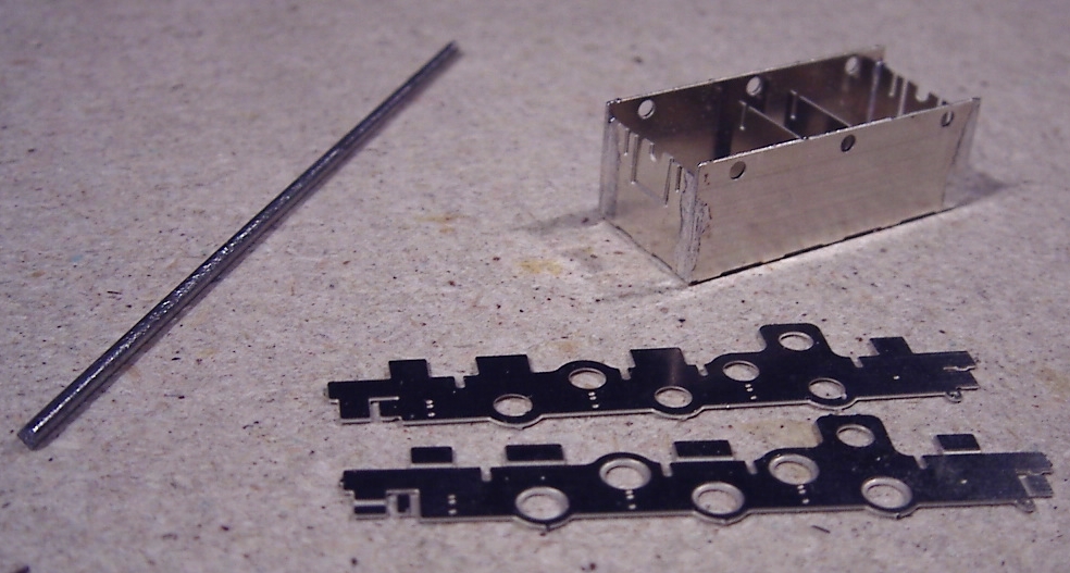
Now to join the sides with the spacer material.
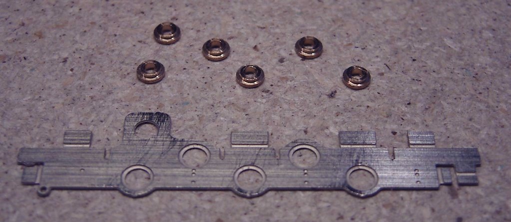
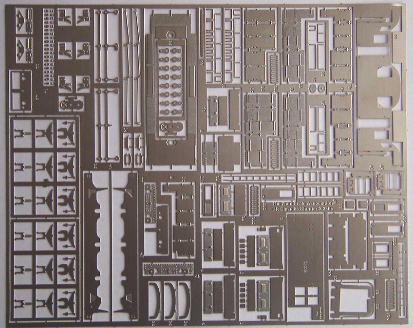
 There are some fold-down flaps on the chassis etch.
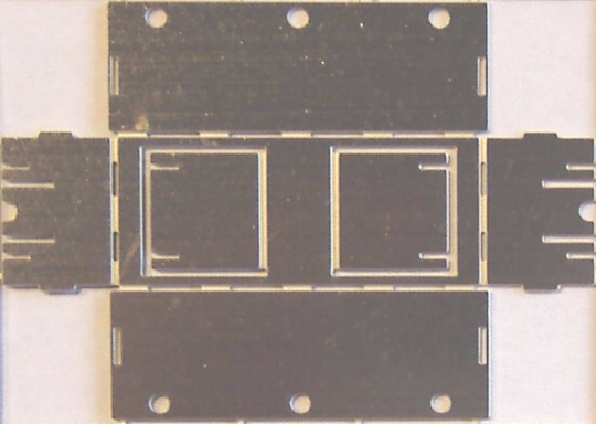
The spacer material is PCB strip with copper-plating on both sides. The recommended method is to cut parallel insulating gaps into the strip. I need to leave enough copper on the outside to be able to solder the strip onto the flaps on the brass sides. Tried a file first but a fine-toothed saw along a straight edge is much quicker. Has to be done on both sides of course to maintain electrical separation.
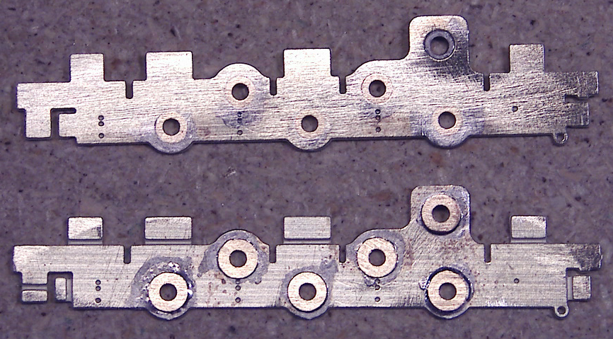
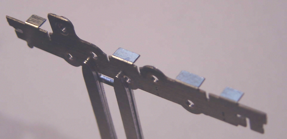
When I tried the strip in position I found that I had cut the gaps too close to the outside, so the flaps might cross the gaps and cause a short-circuit. That’s the last thing I wanted, so before soldering the strips on I enlarged the gaps . Quite generously...

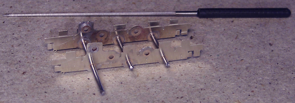
Five horizontal strips in all. I soldered the 2 central strips onto the flaps, as it mentions in the instructions that they may obstruct the gears if fitted underneath.
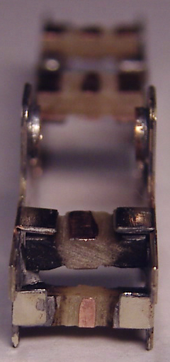
And one vertical strip.