Monday, April 23, 2007

Building the cab


The cab structure is a combination of metal etch with resin roof.
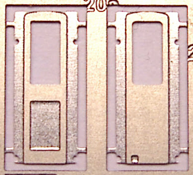

wooden cab door (left) and steel door


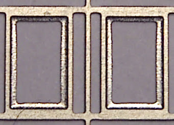
cab window etch

Some locos had a frame around the cab window, but mine is plain glass.

The doors are soldered onto the etch for strength before removing it from the fret.

cab etch with doors

Bending the sides accurately is tricky, particularly avoiding the delicate windscreen wipers. Without a folding tool I’m using 2 pieces of brass bar to support the etch next to the folds. Eventually it goes wrong. One of the doors comes loose and the frame bends.


I’ve removed the door on the right.

With the etch flat on a piece of glass I push a brass bar across the bent side with increasing pressure. When flat I replace the door with epoxy glue.


Doesn't look too bad now. The roof isn't glued at this stage.


I’ve made some windows from 0.25mm clear styrene. I’d like to model one of the cab windows half-down but I’ll need some thinner material for that. In any case I won’t fit the windows until the cab’s painted.


** May 2007 **

Yes my friends, I folded the cab inside-out.

After unfolding it, reversing the doors and folding it back there were three casualties.
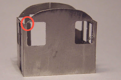

(1) The thin section at the top of the window developed a kink that I haven't been able to remove. I'll have to fill it and file it flat.

(2) One of the windscreen wipers came off, and since they were both too bent by now I decided to replace them with some thin wire.


They're under 3mm long, made from 0.1mm electrical wire. I've glued the arm on top of the wiper so that when fixed the arm will be clear of the glass. I'm working at the boundaries of my dexterity and patience here - really wish my hands were a bit steadier.
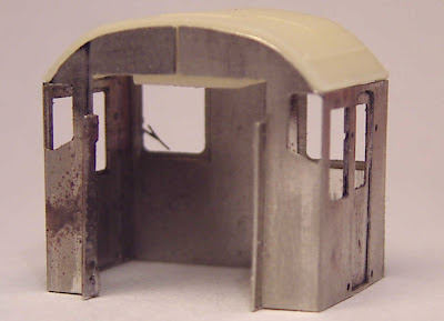


(3) One of the upright tabs came off, but I managed to solder it back.

For a few days I was too annoyed with myself to work on this. Feeling better now though, and ready to move on...

Thursday, April 19, 2007

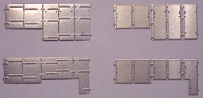
The bonnet sides


left bonnet doors

I’m tempted by the look of the riveted bonnet doors (left), but for my choice of prototype I need the pressed steel doors with cut-out for the air compressor unit (below right).


right bonnet doors

Four options here. I need the pressed steel doors with cut-out for the vacuum exhauster (below right).

There are lots of handles on the bonnet sides.

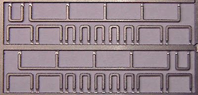
bonnet handles etch


There’s a template for drilling the holes to locate the handles accurately.


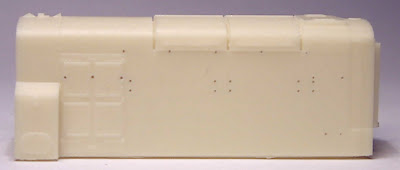
I had to file the lower left-hand edge to allow it to lie with the four square holes matching the grille marks on the body. Securing it with crocodile clips I can drill 0.3mm holes through the body.

My new “archimedean” drill broke the first bit straight away. Obviously a skill I need to learn. Had more success with the bit held in a pin vice, twisting quickly and pressing gently, but one lapse of concentration and another bit snapped. Glad the good people at “Eileen’s Emporium” had advised me to buy their less-expensive bits.

holes drilled


There are 2 options for the bonnet side grille. I need the one with the thin wires inside.


And a cover at the base.


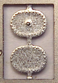
There's a cover on top of the left-hand fuel tank. I'll need the flat one.


The fuel tank cover and bonnet sides are fixed with epoxy. The side grille will need to be removed for painting. I've added one handle for effect - I’ll fit the others later to avoid damage.

Friday, April 13, 2007

Adding extra weight


I've recently been looking at some of my old N-gauge locos. Armed with the confidence and knowledge I've gained through working on this kit I took apart my
temperamental Farish railcar . Happily I did manage to get it back on its wheels, and it was also interesting to look at a different method of chassis design at first hand.

Anyway, it convinced me that I need to get as much extra weight onto this loco as possible.


I recently bought this lead shot. I thought it might fill various gaps more effectively than a single thickness of lead sheet, and also I didn't fancy cutting it to size.

First I’d like to have some extra weight below the footplate, giving it a lower centre of gravity and hopefully more stability.


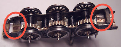
There are sections at each end of the chassis that could easily be used.


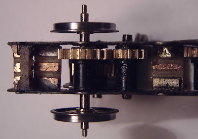
A simple styrene sheet base with dividing strip to maintain the "split frame"


I glue the shot one layer at a time.


I'd been advised to use PVA glue, but it didn't hold strongly enough so I'm using epoxy.


The boxes on the footplate are straightforward.


The motor itself is fairly heavy, but if I need it I'll also have room for extra weight around the terminals under the bonnet, and hopefully also in the cab to balance it out.

Sunday, April 01, 2007

Fitting the wheels


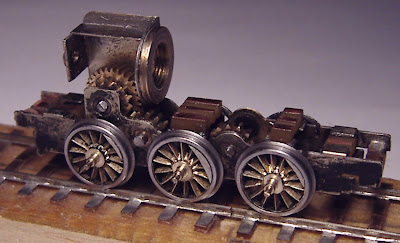
I've been thinking about how to fit the wheels for some time ("putting it off" might be more accurate). Seems that people have their own methods, and the instructions touch on this only briefly. I've looked at the design for a jig that fits wheels (and does the quartering) by tightening it a vice. But an Association member who builds his own locos successfully with relatively simple tools has described his method for fitting and quartering wheels which I plan to follow.

First file a chamfer on the end of each wheel axle


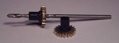
I'd already opened up the muffs with a 1.5mm drill. Now I need to drill a 1mm hole through the centre of the muff. This is to allow release of air as the tight-fitting axles are pushed in.


A final check that the chassis sides are still electrically separate, then I fit the first axle by turning each wheel by hand with gentle pressure inwards.


I've put a small washer on this axle to reduce sideways play.

I'd previously calculated that I needed a 0.45mm gap on each side between the wheels and chassis and now I need some spacers.

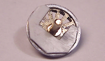
simple styrene sheet spacer

The key dimension is the distance between the back of the wheel rim and the chassis side. So the gap in the spacers has to be big enough to go around the small raised section visible around the axle, allowing the spacer to lie flat against the wheel. I cut some from 0.5mm thick styrene sheet.

Now with the spacers in place I can gently twist both wheels inwards until they are tight against the spacers. The first axle turns freely so I do the same with the central axle.

spacers on central axle

Now the gears are locking. Even though they had previously been running smoothly, I have to spend quite a while running the wheels along the test track by hand to loosen them up again.

Next to add the final axle, tighten the wheels to 8.5mm back-to-back (or just over) and turn the wheels so that the balance weights are aligned on both sides, with a quarter-turn difference between sides.